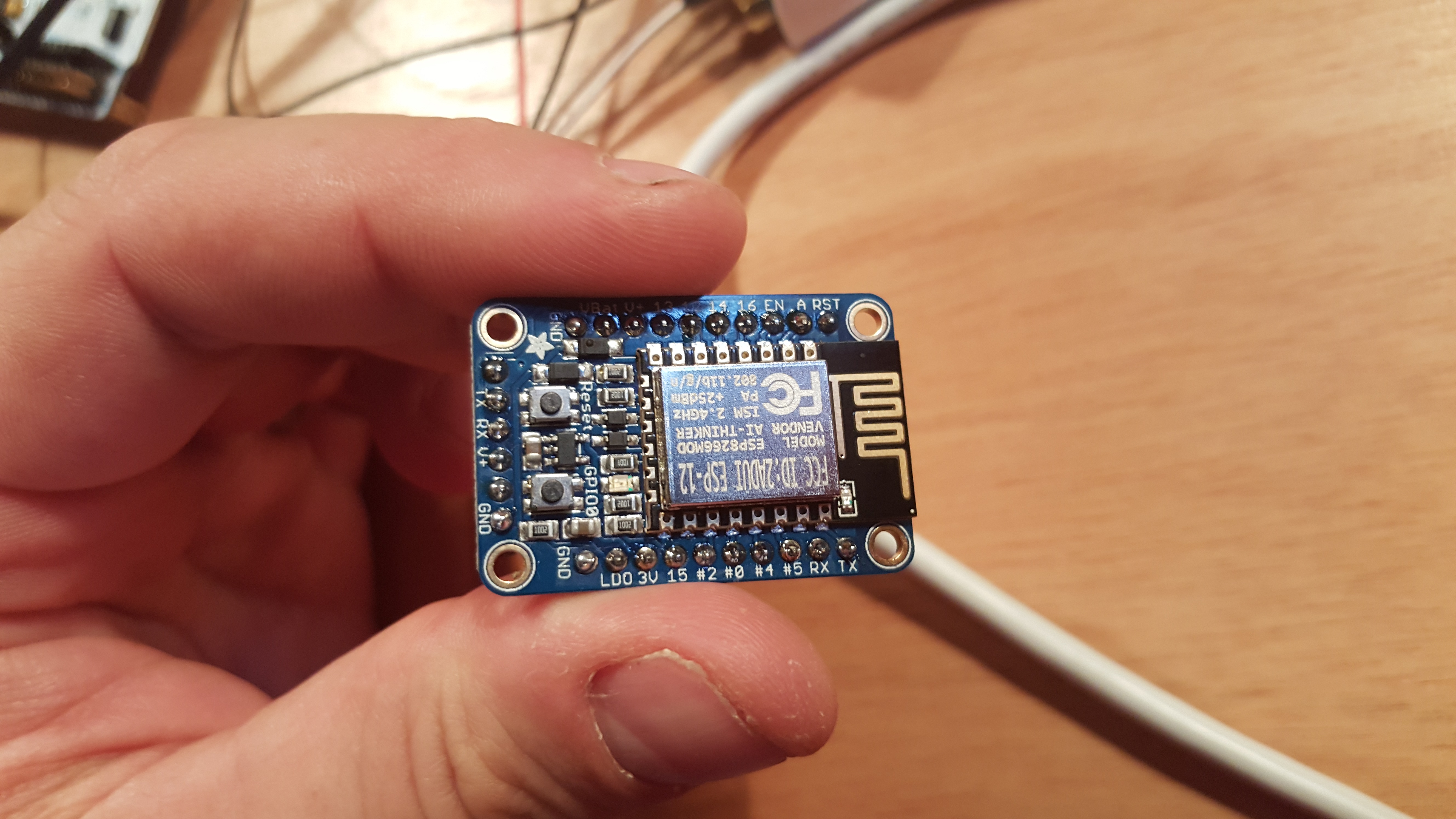
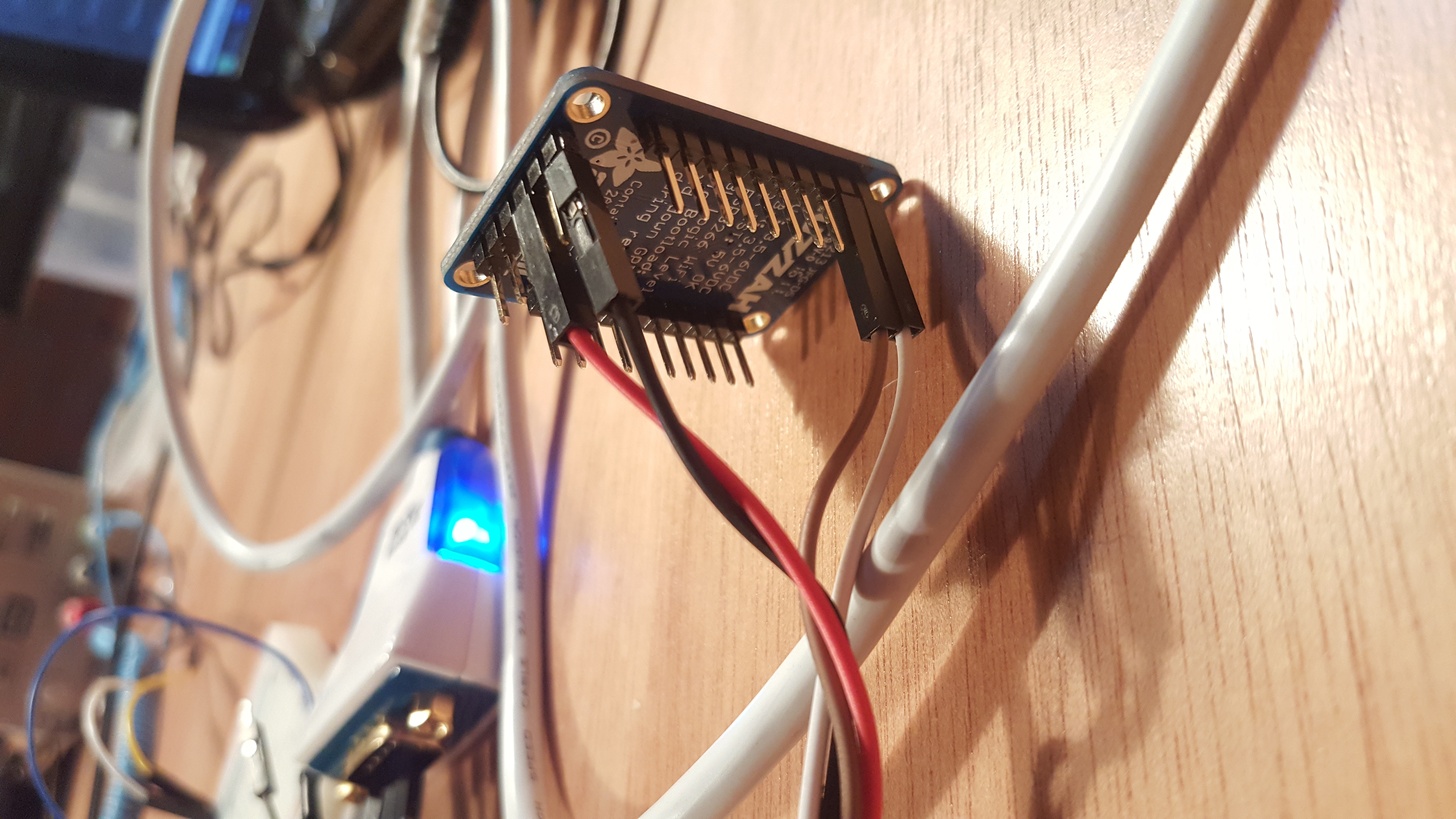
Huzzah ESP8266 problems solved
Lets get that Huzzah working! Hooked it up, but all kinds of errors… so here is how I hooked it up and working wel… I have to detach the TX (on board) before I can get in “programming mode”!! Then it went well. You can also use the RX/TX on the other side. Also works (tested it!)
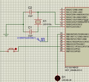
Proteus/ISIS crystal clear…..
Ok ever had the idea to let a MCU work with an external crystal in Proteus/ISIS? You did everything right (HS config and register settings) and it is not working…. The X1 (CRYSTAL) component is not working as I expected….
[The settings can be different at your project. And the simulation is slower than in real life [breadboard]]
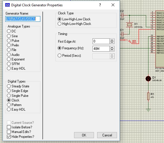
The solution: use a generator! [U1(RA7/CLKI/OSC1)]
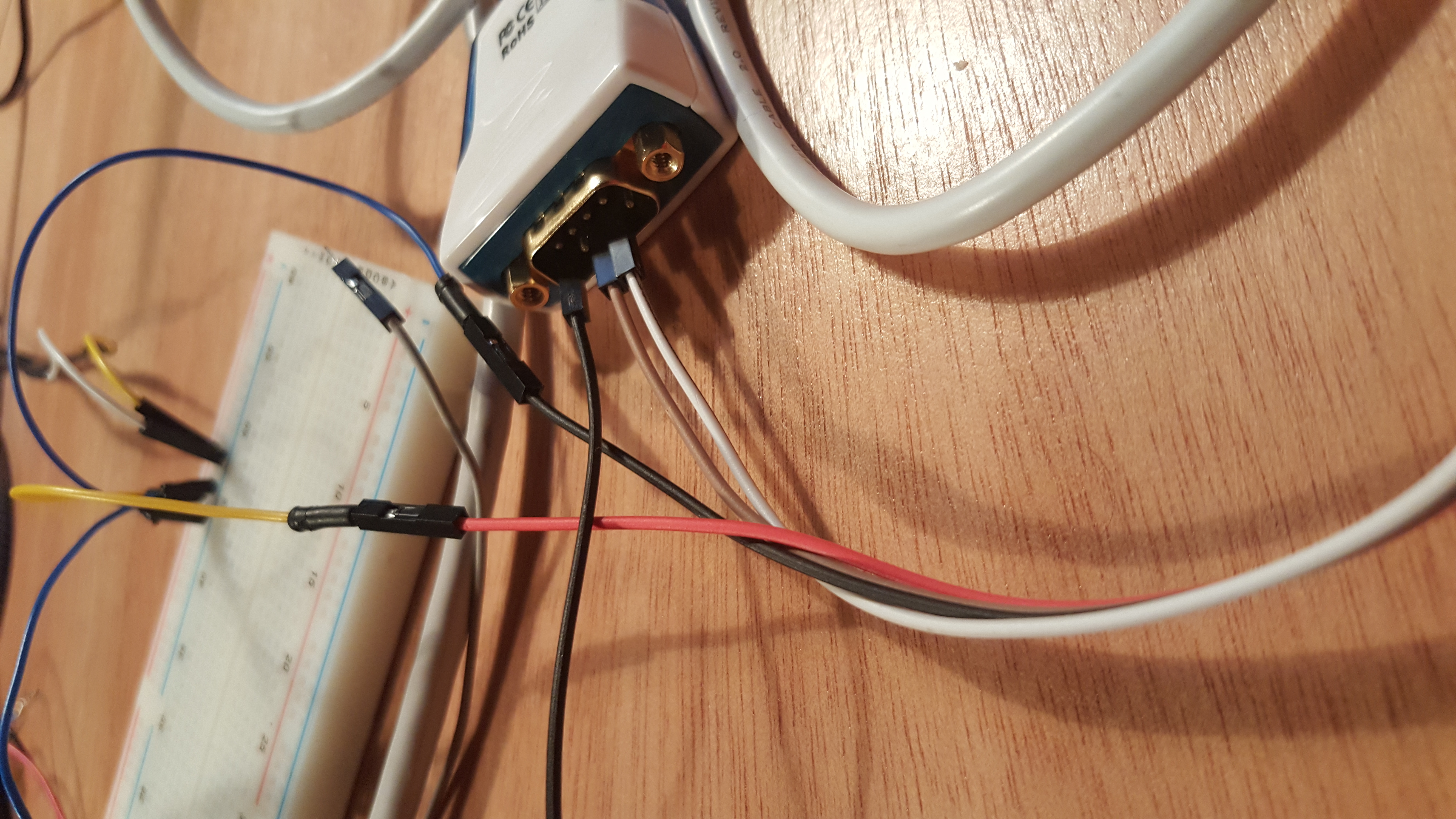
STM32 USART thingy…..
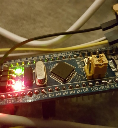
After a short analysis it appears that the logic analyzer shows that the baudrate is correct, but the ascii chars are gibberish and the endian order is messed up. This document will contain a possible solution.
Solution
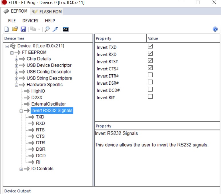
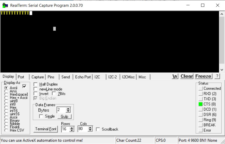
It seems that the FTDI cable is inverting the signal. After programming the cable with FT-Prog (software) all communication went well. In Realterm and in Putty.
Screenshot settings within FT-Prog (url):
Realterm (url):
Code:
/*****************************************
* stm32 timer led + usart example main.c
* Bvdv -- 2016(c)
* http://www.han-ese.nl/STM32/stm32f10stdlibrary/html/index.html
*****************************************/

#include "stm32f10x.h"
#include "stm32f10x_gpio.h"
#include "stm32f10x_tim.h"
#include "stm32f10x_rcc.h"
#include "stm32f10x_usart.h"

/* User defined function prototypes */

/* Prototypes for func. from stm32f10x lib. */

void MX_GPIO_Init(void); //Initializes the GPIOx peripheral
void MX_UART_Init(void); //Initializes the USARTx peripheral
void led_toggle(void);
uint16_t data;

/* Delay method. Custom made */
void simple_delay(uint32_t us)
{
/* simple delay loop */
while (us--) {
asm volatile ("nop"); //nop is an assembly instruction that does nothing
}
}

/* Main method */
int main(void)
{
RCC_DeInit(); //Resets the RCC clock configuration to the default reset state.
MX_GPIO_Init();
MX_UART_Init();

while(1)
{
led_toggle();
simple_delay(1000000);
}
}

/* Initializes the USARTx peripheral */
void MX_UART_Init(void)
{
//Enables or disables the Low Speed APB (APB1) peripheral clock.
RCC_APB1PeriphClockCmd(RCC_APB1Periph_USART2 | RCC_APB2Periph_AFIO, ENABLE); //BELANGRIJK!!!!

//USART Init Structure definition
USART_InitTypeDef UART_InitStruct;

UART_InitStruct.USART_BaudRate = 9600; //Hoeft niet meer/1.04;
UART_InitStruct.USART_WordLength = USART_WordLength_8b;
UART_InitStruct.USART_StopBits = USART_StopBits_1;
//USART_OverSampling8Cmd(USART2,DISABLE); //Enables or disables the USART's 8x oversampling mode.
UART_InitStruct.USART_Parity = USART_Parity_No ;
UART_InitStruct.USART_HardwareFlowControl = USART_HardwareFlowControl_None;
UART_InitStruct.USART_Mode = (USART_Mode_Tx | USART_Mode_Rx);

//Initializes the USARTx peripheral according to the specified parameters in the USART_InitStruct .
USART_Init(USART2, &UART_InitStruct);

/* Enables or disables the specified USART interrupts. Enable RXNE interrupt */
USART_ITConfig(USART2, USART_IT_RXNE, ENABLE);
/* Enable USART1 global interrupt. Enable IRQn */
NVIC_EnableIRQ(USART2_IRQn);
//Enables or disables the specified USART peripheral.
USART_Cmd(USART2,ENABLE);

}

/* Initializes the GPIOx peripheral */
void MX_GPIO_Init(void)
{
//Enables or disables the High Speed APB (APB2) peripheral clock.
RCC_APB2PeriphClockCmd(RCC_APB2Periph_GPIOA | RCC_APB2Periph_GPIOC, ENABLE);

//GPIO Init Structure definition
GPIO_InitTypeDef GPIO_InitStruct;

//Fills each GPIO_InitStruct member with its default value.
GPIO_StructInit(&GPIO_InitStruct);

//PA03 = USART2.RX => Input
GPIO_InitStruct.GPIO_Pin = GPIO_Pin_3;
GPIO_InitStruct.GPIO_Mode = GPIO_Mode_IN_FLOATING;

//PA02 = USART2.TX => Output
GPIO_InitStruct.GPIO_Pin = GPIO_Pin_2;
GPIO_InitStruct.GPIO_Mode = GPIO_Mode_AF_PP;
GPIO_InitStruct.GPIO_Speed = GPIO_Speed_50MHz;
GPIO_Init(GPIOA, &GPIO_InitStruct);

GPIO_PinRemapConfig(GPIO_Remap_USART2,ENABLE);

//PC13 = LED
GPIO_InitStruct.GPIO_Speed = GPIO_Speed_50MHz;
GPIO_InitStruct.GPIO_Mode = GPIO_Mode_Out_PP;
GPIO_InitStruct.GPIO_Pin = GPIO_Pin_13;

//Initializes the GPIOx peripheral according to the specified parameters in the GPIO_InitStruct.
GPIO_Init(GPIOC, &GPIO_InitStruct);

}

/* Toggle LED */
void led_toggle(void)
{
/* If PORTC BIT 13 clear, set it */
//Sets the selected data port bits.
GPIO_SetBits(GPIOC,GPIO_Pin_13);
simple_delay(100000);
//Clears the selected data port bits.
GPIO_ResetBits(GPIOC,GPIO_Pin_13);
simple_delay(100000);

}

void USART2_IRQHandler(void)
{

/* RXNE handler */
//Checks whether the specified USART interrupt has occurred or not.
if(USART_GetITStatus(USART2, USART_IT_RXNE) != RESET)
{
/* If received 't', transmit 'T' */
//Returns the most recent received data by the USARTx peripheral.
if((char)USART_ReceiveData(USART2) == 't')
{
//Transmits single data through the USARTx peripheral.
USART_SendData(USART2, 'T');

/* Wait until Tx data register is empty, not really
* required for this example but put in here anyway.
*/

//Checks whether the specified USART flag is set or not.
while(USART_GetFlagStatus(USART2,USART_FLAG_TXE) == RESET);

}

}

}